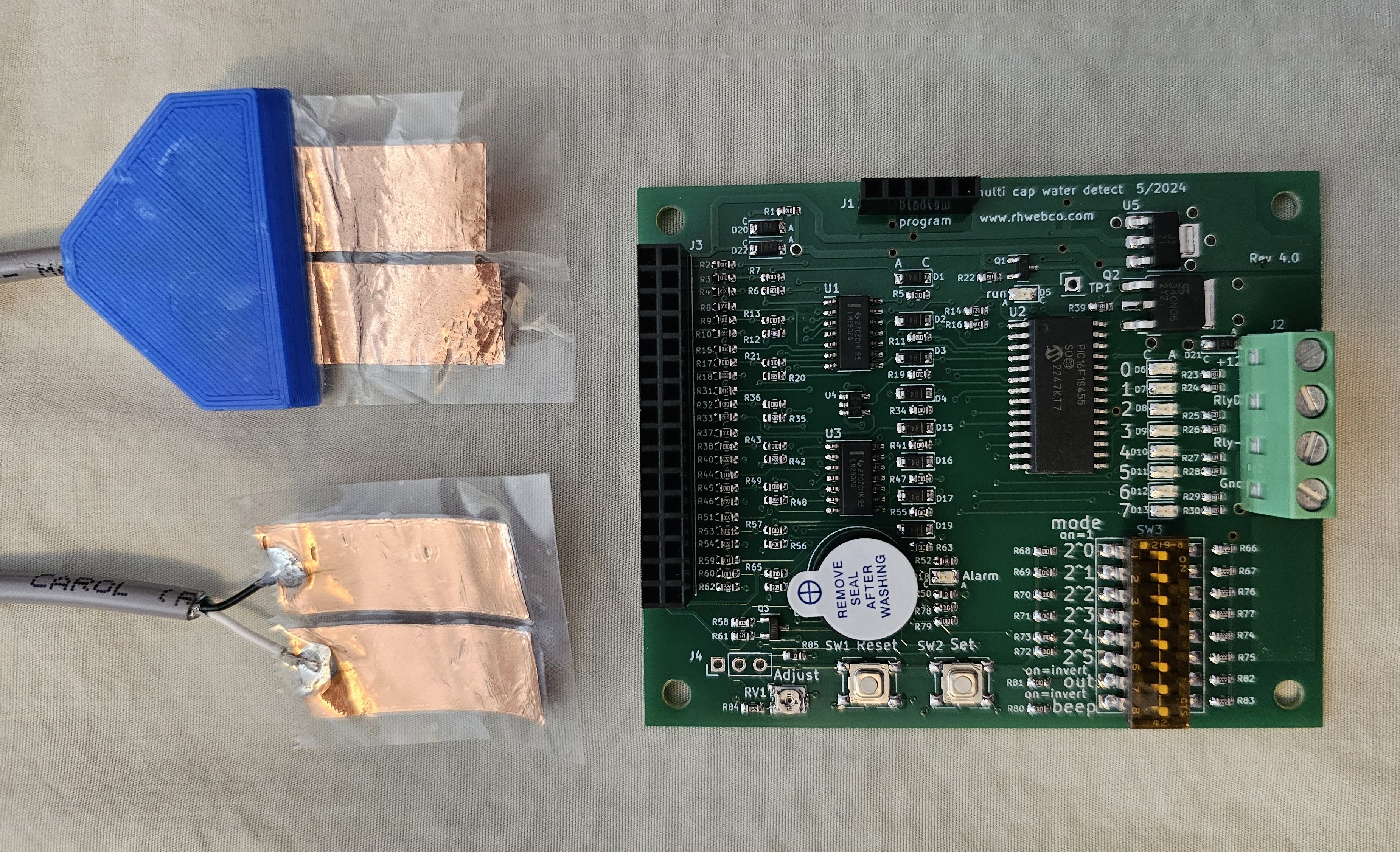
CapWater board
This is an 8 channel capacitive water or soil moisture sensor and control board. This board is as described in the video on YouTube. The user may select various modes via the DIP switch. Both the turn-on and the turn-off thresholds for each channel are adjustable and are saved in EEPROM memory. The board can be used for experimenters to set up a hydroponic or plant watering system.
The purpose of this board is to turn off a pump, or turn on an alarm if any leaks are detected. It may also be used to turn on a pump if any of the sensor inputs are dry.
There are 8 inputs for capacitive type sensors. These sensors can be easily made by hand from ½ inch wide copper tape and some shipping tape. If the sensor is to be buried or will normally be wet, silicon sealant should be used to prevent water seepage where the wires enter the shipping tape. There is no metal in direct contact with the water or the soil.
A programming port is provided so that the user may modify the program to include custom modes. The programming port was designed for the MPLAB PICKIT 4 (trademark of Microchip Corp). The board was designed for the Microchip Technology PIC16F18455T-I/SO in the 28 pin SOIC package.
YouTube video: https://youtu.be/2mlbzIgxmAk
The “C” program, PIC project files, Bill of Materials and schematic may be downloaded here: capWater.zip
Fully built and tested: https://www.ebay.com/itm/176383017835
Bare board https://www.ebay.com/itm/176383023943
Inputs:
There are 8 inputs:
Each input has a driver plate connection, a sensor plate connection and two ground (shield) connections.
Each input may be connected to a cable that is up to 10 feet long with a sensor plate dimension of 13mm x 30mm (½ x 1 3/16 inch) for each of the two plates. In the case of measuring soil moisture, a larger plate area may be desirable if the cable is 7 ft or longer.
Any input can be shorted from driver to sensor for an always wet condition.
Any input can be left open for an always dry condition.
Output:
The power/output connector pins, J2 pin 1 and J2 pin 2, should be connected together. These two pins should be connected to the positive 12v supply and also to the positive pin of the motor or relay. The negative pin of the motor or relay should be connected to J2 pin3. The return for the 12v (ground) should be connected to J2 pin 4.
In the case of a 24v motor or relay, pin 1 should be connected to +12v, pin 2 should be connected to +24v and to the positive pin of the motor or relay. The negative pin of the motor or relay should be connected to J2 pin3. The return for the 12v (ground) and the return for the 24v should be connected to J2 pin 4.
A 5A fuse is recommended in case the motor or relay becomes shorted.
Dip Switches:
The switches are only read during reset or when powering up.
If you change a switch, press the reset button, or turn the power off and on for the effect to be seen.
SW1 is an 8 channel Dip switch, labeled as 1 through 7. The mode switches are a 1 for the position marked “on”:
switch 6: invert the output:
If switch 6 is off, the output is driven to ground when output is on.
If switch 6 is on, the output is high impedance when output is on.
Switch 7: invert the beep:
If switch 7 is off, the beeper will sound when beep is on.
If switch 7 is on, the beeper will sound when beep is off.
jumper R50: if this 0-ohm resistor is removed, there will be no beep. The alarm LED, D18, will continue to work normally.
Switches 1 through 6 are a binary number that will set the mode.
Sw6 Sw5 Sw4 Sw3 Sw2 Sw1
2^5 2^4 2^3 2^2 2^1 2^0
Mode 000000:
And function: output_on if all inputs wet
Output will be on only if all inputs are wet.
If a sensor is un-used, place shorting jumper, example: if sensor_0 is un-used, jump J3pin2 to J3pin4
Mode 000001:
Or function: output_on if any input wet
If a sensor is un-used, just leave it un-connected.
Mode 000010:
Fill reservoir from supply tank:
Sensor_7 is placed at bottom of the supply tank. if sensor 7 is dry (supply tank empty): pump will turn off and beep will sound.
Sensor_6 is placed at low level for the reservoir.
If sensor_6 is dry and sensor_7 is wet, pump will turn on.
Sensor_5 through sensor_2 can be placed to indicate water level (will not effect pump or beep)
Place sensor_1 at high level of reservoir. if sensor_1 is wet: pump will turn off
It is an error if sensor6 is dry and sensor_1 is wet, so pump will turn off and beep will sound
Mode 000011:
Fill reservoir from supply tank:
Same as 0010 accept that if pump is turned on and sensor_0 remains dry for 30 seconds (pump broken) turn off pump and beep
place sensor_0 where the water from the reservoir fill pipe (pump output) enters the reservoir.
place so that water will fall on the sensor when the pump is running.
Mode 000100:
Fill reservoir from supply tank:
Same as 0011 accept that if pump is turned on and sensor_0 remains dry for 90 seconds,
indicating a broken pump, the pump will turn off and the beep will sound.
Mode 000101:
Control nutrient pump:
When power is applied, pump will turn on.
Place sensor_0 at the output of the pump hose. This is the flow sensor.
If sensor_0 becomes dry for longer than 30 seconds (pump broken) turn off the pump and turn on the beep.
Place sensor_7 at the bottom of the reservoir. If sensor_7 is dry (reservoir empty) pump will turn off and beep will sound.
Place sensor_1 through sensor_6 at places where leaks should be detected.
If any of the sensors, sensor_1 through sensor_6 becomes wet, pump will turn off and beep will sound.
Un-used leak sensors should be left un-connected.
Mode 000110:
Control nutrient pump:
Same as 000101 accept that the wait time is 90 seconds instead of 30 seconds. This is useful if it takes a while from when the pump
turns on until the water begins coming out of the pipe.
Mode 001000 through 001111:
Use pot to adjust the turn-on threshold, then press the “set” button to save the threshold. Mode 001000 is for channel 0 and mode 001111 is for channel 7. Always set the turn-on threshold before adjusting turn-off threshold.
Mode 010000 through 010111:
Use pot to adjust the turn-off threshold then press "set" button to save.
Mode 100000:
Turn on the pump when any plant is dry and reservoir is not empty (channel 0 is the reservoir)
Mode 100001:
Same as 100000 accept channel 1 is the flow sensor with time-out of 30s
Mode 100010:
Same as 100000 accept channel 1 is the flow sensor with time-out of 90s
Note 1: Remember to press "reset" button after changing switches, as they are only read during power-up.
Note 2: The on-board pot may be disabled by removing the jumper R85. A custom pot may then be connected to J4 with the wiper connected to J4 pin 2.
Note 3: For setting the thresholds, the lower three mode switches use binary numbers to indicate the channel number as follows:
Sw3 Sw2 Sw1
0 0 0 channel 0, sensor pin J3 pin 2, driver pin J3 pin 4, shield (ground) J3 pins 1 and 3
0 0 1 channel 1, sensor pin J3 pin 6, driver pin J3 pin 8, shield (ground) J3 pins 5 and 7
0 1 0 channel 2, sensor pin J3 pin 10, driver pin J3 pin 12, shield (ground) J3 pins 9 and 11
0 1 1 channel 3, sensor pin J3 pin 14, driver pin J3 pin 16, shield (ground) J3 pins 13 and 15
1 0 0 channel 4, sensor pin J3 pin 18, driver pin J3 pin 20, shield (ground) J3 pins 17 and 19
1 0 1 channel 5, sensor pin J3 pin 22, driver pin J3 pin 24, shield (ground) J3 pins 21 and 23
1 1 0 channel 6, sensor pin J3 pin 26, driver pin J3 pin 28, shield (ground) J3 pins 25 and 27
1 1 1 channel 7, sensor pin J3 pin 30, driver pin J3 pin 32, shield (ground) J3 pins 29 and 31
Note 4: If sensors from multiple boards are placed into the same tank, use the driver pin from only one board for all the sensors in the same tank. This is because the driver from one board will interfere with the driver from a different board.
Note 5: This board is designed for experimenters to set up and modify as required. The board has not been certified as being fit for any specific purpose. The warranty is for 60 days and is for replacement or refund of the purchase price only.